from The Washington Aqueduct 1852-1992, by Harry C. Ways, page 55.
| Introduction | Historical Background | Chronology | Geography | Biography | Technology | Ownership and Financing | General Bibliography |
| Technology | Water Motors |
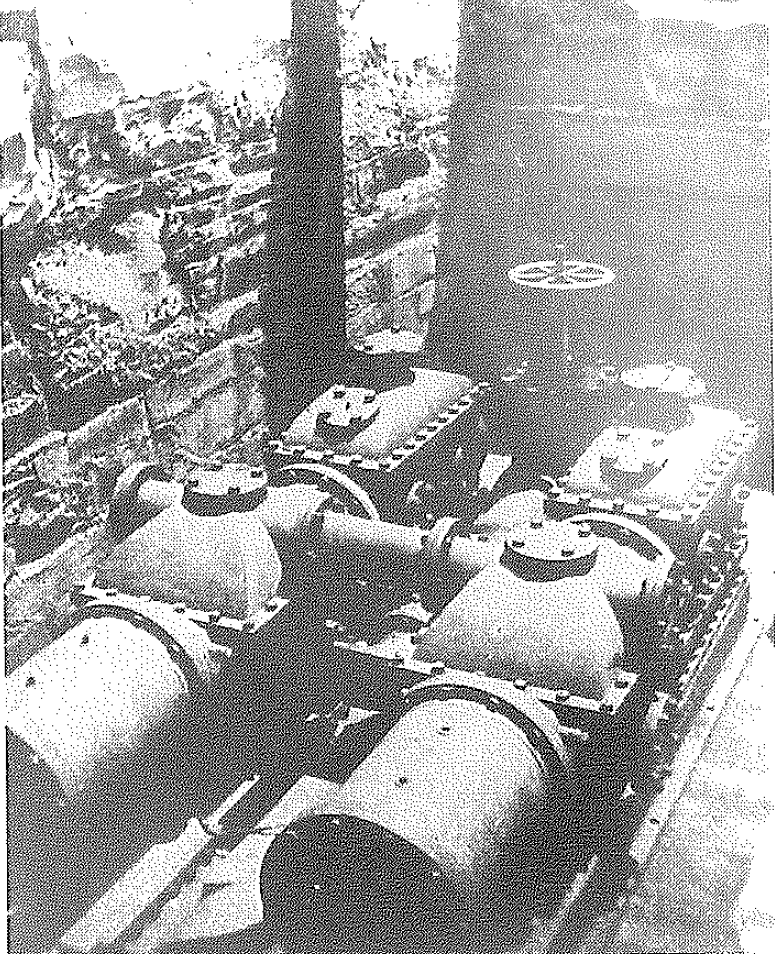
Water motors. also called water pressure engines or water engines, were adapted from early water meters in the 1850s and used to power sewing machines, printing presses, ventilation fans, and other devices using water pressure from public water systems. Some were quite large, as shown in the image below, but most were fairly small, including the Backus Water Motor that was probably the most popular in America.
|
| The Worthington Pumping Engine as installed in Rock Creek Bridge
c. 1859, from The Washington Aqueduct 1852-1992, by Harry C. Ways, page 55. |
References
1812 "Certain
Improvements in the Methods of Constructing, Laying down and Organizing
the Main and other Pipes for the Conveyance of Water for the Supply of
the Metropolis of London and other Cities, Towns, and Places where
Public Waterworks are adopted, and of Applying the Water so conveyed to
a Variety of other useful Purposes, to which the same has never before
been So applied," British Patent #1145, October 31, 1812, by Joseph
Bramah, Pimlico.
1825 "Bramah's Hydraulic Crane," from The Scots mechanics' magazine, and journal of arts, sciences and literature 12:131 (December, 1825)
1838 "Armstrong's Improved Water-Wheel," by W.G. Armstrong, Mechanics' Magazine 30:209-212 (December 29, 1838)
1847 "Bishop's Hydraulic Engine," from Scientific American 2(40):313 (June 26, 1847)
1849 "Hydraulic
Engine," from Scientific American 4(34):266 (May 12, 1849)
The Glasgow (Scotland) Citizen, says: "In noticing the hydraulic cranes at
the General Terminus Rail way Company's Wharf, some months since, we
stated our conviction that the time was not distant that the new power or
new application of power - the pressure of water in air tight pipes -
would be made largely available as a motive force. We have now the
satisfaction of stating that there is no longer any doubt as to the
applicability of this power to machinery. We have had the pleasure of
inspecting a model engine in the office of the Corbals Gravitation Water
Company, Portland-Street - and which is the most beautiful and simple
contrivance we ever saw. The model is about one-horse power, with a
horizontal cylinder, and having a twelve-inch stroke. The water, which
here has a pressure of about 201 feet, is introduced to it from a common
house-pipe; and such is the simplicity of the machine, that a child could
work it and regulate its speed at pleasure by the mere turning of a
handle. The great advantage of this engine consists in the fact that it
call be put up in any flat of a house on any street, - wherever, in fact.
there is a water-pipe. It takes up very little room; it
registers the quantity of water it used (which by the way, may be again
available for several purposes, as it leaves the engine, as pure as when
it entered;) and it may be erected in those localities in cities where
steam-power is prohibited on account of danger and nuisance from smoke,
and without raising the rate of insurance. It will be much cheaper in
every respect than a steam-power engine. The model has been constructed by
Messrs. James Steel and Sons, Dundee. In all processes requiring engines
of from two to six or eight horse-power such as coffee-grinding, baking,
turning, letter-press machine printing &c, the gravitating water power
engine must speedily come into general use."
The engraving and description of an hydraulic engine, will be found on
page 213. vol. 2 Scientific American, invented by Mr. E.
Bishop. We have heard that there are two such engines in operation
in Liverpool, England, and in some other places. They are in successful
operation, and might be very useful in some parts of our country.
1851 Boston Evening
Transcript, January 28, 1851, Page 2.
The Traveller press is driven by a new power called a Water Metre or Power
Metre, the invention of Mr. Samuel Huse, of this city. The water
wheel, which lies in an iron cylinder, is about the size of a half bushel
measure, an is operated by the Cochituate water, through a two inch
pipe. It is a simple but very beautiful contrivance, and is of about
two horse power.
1851 "New
Motive Power for the Fast Presses," New-York
Herald, January 29, 1851, Page 3.
[From the Boston Traveller, Jan. 25]
This monster press (Hoe's fast printing press) is driven by a novel and
moat convenient and powerful little machine, which is seen on the right of
the printing press, consisting of a small cylinder, with cog-wheels and a
pulley attached. It is called a water metre or power metre, and was
invented by that ingenious mechanic, Mr. Samuel Huse, of this city, well
known for his efficient labors as assistant superintendent of the
Cochituate water works Thia machine was originally invented as a water
measurer; and this is the first application of it as a motive power, it
being found to possess this power to a most unexpected and extraordinary
degree. It is simple, yet wonderfully efficient. It consists of a hollow
cylinder, 10 inches wide and 16 inches in diameter; inside of which is a
flange cylinder, about 6 inches in diameter. This inner cylinder has
flanges, on which are four valves, extending from one end to the other of
the cylinder, and attached to it by hinges. These valves, when folded, or
shut into the cylinder, form a little more than half its surface. Upon one
side of the metre, the space between the inside of the hollow and the
surface of the flange cylinder, is so filled as to occupy something more
than the width of one of the valves. This filling is made to fit so
exactly as to prevent the water from passing upon one side of this
filling, the water enters the metre, and upon the other side the water is
discharged. The metre is so placed that the valves will, by the force of
gravity, open as they reverse from under the solid filling, and shut upon
the opposite side previous to coming in contact with it. When thus
arranged, the water is let into the cylinder, and comes in contact with
the open valves; the inner cylinder revolves until the water escapes upon
the opposite side: and of course, for every revolution of the interior
cylinder, a given quantity of water must pass through the metre.
This is carefully marked by means of a clock which is attached to the
cylinder, and which will indicate the precise quantity of water which has
passed through the machine in any given time.
The revolving flange cylinder is connected, externally, with cog wheels, a
shaft, and pulley; and from the pulley a belt extends to the driving wheel
of the printing machine.
This metre, or water wheel, is driven by the Cochituate water, introduced
from a aix inch distributing pipe through a two inch lead pipe; and the
flow of toe water is regulated by means of a screw gate near the metre.
This wheel, though so small as to occupy only about 24 inches of room,
affords about three horse motive power.
1851 "Great Mechanical
Improvement - A new use of the Boston Aqueduct," New-York
Daily Tribune, February 6, 1851, Page 6.
Since the introduction and use of the Cochituate water in Boston, it
became very necessary to ascertain precisely the quantity of water made
use of daily by the large establishments in Boston, as the engineers and
the owners could not agree as to the probable amount. Those having the
water-works in charge, instead of waiting tor accident to produce a
machine suited to the purpose of measuring the water, sought among the
mechanics in their employ and in the State, for one possessed of the skill
most likely to succeed in the enterprise. Mr. Samuel Huse, formerly a
citizen of Newburyport, was selected for this undertaking. He has
succeeded in producing an instrument which admirably answers the purpose.
By the employment of this machine in Boston over most of the street of
which tbe water in the pipes has a head of from 80 to 100 feet, it has
been discovered by Mr. Huse that the water would pass the meter or
measurer with such force as to superadd an efficient power. He has
perfected, according to the statements of a correspondent of the Newburyport
Herald, his invention and secured letters patent, and has set his
meter in operation for driving the printing press of a daily paper in
Boston. Through a two inch lead pipe, a stream of Chochituate water is
introduced into a meter which only occupies 24 square inches. The
fall of water between the Boston reservoir and this meter is about a
hundred feet. This two inch stream will discharge 60 gallons of
water each minute, and in passing through the meter will gave a motive
power equal to what is called three horse power. This is more than
sufficient for driving the press. It is less hazardous than a steam
engine, requires no attention and is always in readiness. It can be used
where steam engines would not be allowed.
This invention will be of immense service to the various mechanical and
manufacturing establishments in Boston, enabling many more of them than
formerly to make use of this power in their various processes. The
invention is one of much scientific and mechanical interest, while to us,
we must confess there is a trifle additional interest from the fact that
it comes from a citizen of our native town.
1851 "Printing by Water Power," Newark Daily Advertiser, February 4, 1851, Page 2.
1851 "New Water Machine for Driving a Printing Press," from Scientific American 6(22)169 (February 15, 1851)
1854 "Newly Invented Stationary Fire Engine," American Artisan (New York City, New York), January 7, 1854, Page 5.
1855 "Water Pressure Engine," from American Farmers' Magazine 7(12):754 (June 1855)
1855 "Reports
of the Joint Standing Committee Upon the Water Question," The
Sun (Baltimore, Maryland), September 4, 1855, Page 1.
There is another source of revenue, however, from which, it is in the
opinion of this committee, large receipts will be obtained, which is the
sale of the surplus water for power purposes. The practicability of
applying water pressure as a moor the committee consider to be thoroughly
and most satisfactorily demonstrated by the working of a water-pressure
engine in daily operation in the city of Boston. This committee
examined this subject with great care, and obtained the information they
possess by personal examination, fully impressed with the importance of
this subject to the interests of the city of Baltimore. The engine
referred to is of four-horse power, and is used for propelling the press
of the Evening Traveller newspaper, having a daily edition of 14,000
copies. The proprietor stated to the committee that water-pressure
engines possessed many advantages over steam engines, and that at the rate
of one cent per hundred gallons, which is the price paid for the water, he
found the cost about twice as great as that of steam.
The Boston City Engineer stated that application has been made by other
persons for the use of water as a motor at these rates, but that the
supply was not sufficient to admit its further use for that purpose.
The elevation of the water in the Reservoir at Boston is 115 feet above
the tide. In Baltimore the height will be 176 feet, consequently the
power to be afforded b any given quantity of water will be greater in the
latter named city then in the former by over 50 per cent, and at
corresponding valuation could be sold for 1½ cents per hundred gallons.
If the city should sell surplus water of the Gunpowder for power purposes
at one-fourth this price, at which rate it would be greatly cheaper than
steam power, there would be required the sale of only 22,000,000 gallons
of water daily to afford revenue sufficient, from this source alone,
to pay the interest on the cost of the works as herein proposed.
This quantity of water, if expended during twelve hours, would yield 2,000
horse power, or less than half the steam power now used within the city
limits.
Reference can be made to cities in Europe where water is sued as a motor;
bu without entering into further details, the committee believe they have
submitted facts sufficient to demonstrate both the applicability of water
for this purpose and the certainty of its extensive use when the
opportunity may be presented. Nor do they deem it necessary in this
connection to dwell upon the great advancements of the general prosperity
of all interests in this city, which would result from a material
diminution of the cost of power for mechanical or manufacturing purposes.
1858 Washington
Aqueduct, Annual report of operations during the year ending September
30, 1858, by M. C. Meigs, 35th Congress, 2nd Session, H. Ex. Doc. 2
Page
997: Contract for Water Pressure Engine, June 5, 1858.
1860 "The Great Washington Aqueduct Bridge," by M.C. Meigs, January 27, 1860, from Scientific American 2(6):86-87 (February 4, 1860)
1860 "A
Great Iron Aqueduct Bridge," The Daily Dispatch (Richmond,
Virginia), January 30, 1860, Page 4.
Washington Aqueduct Bridge, over Rock Creek, at the western end of
Pennsylvania Avenue.
The abutments contain vaults, in which are the connecting pipes and
stop-cocks for regulating the flow and discharge of water, and inside the
western abutments on the Georgetown side, one of the vaults serves as an
engine room and contains a water-pressure engine - the first, it is
believed, erected in this country.
This engine, drawing its supply from the cast iron street mains of the
Washington aqueduct, pumps ten thousand gallons of water per hour into a
reservoir on the heights of Georgetown, a mile distant, and two hundred
and four feet above the machine.
1860 Georgetown
Water Works: Report of the Water Board of Georgetown, D.C., to the
Councils, with the Report of the Engineer, February 10, 1860
Page 10: The pumping engine which supplies it is a water-pressure
engine, capable of supplying, at its ordinary working speed of eleven
strokes per minute, ten thousand gallons of water per hour, or two hundred
and forty thousand gallons per day.
This rate of supply is much more than sufficient for the present domestic
use in the portion of the city above the level of 100 feet, but not
sufficient for extinguishing large fires. For these the store to be kept
in the reservoir is needed.
1860 "New Aqueduct Bridge at Washington, D.C.," from The American Gas Light Journal 1(9):187 (March 1, 1860) Unattributed reprint of January 27, 1860 Scientific American article by M.C. Meigs.
1860 "Water Wheels and
Printing Presses," Grand
Haven News (Grand Haven, Michigan), March 28, 1860, Page 2.
The Lynchburg Virginian is printed on an Adams press which is
driven by a small water wheel, under a high head, with only an inch
discharge pipe. The water is conveyed from an elevated reservoir by
a pipe, and it passes out into the sewer of the street, after having
operated the wheel. This is the most simple mode of driving small
presses where a considerable head of water may be obtained. In New
Castle, England, and in Stirling, Scotland, two weekly newspapers are
printed on presses driven by small water engines, but a small turbine
wheel is about the best form of a water motor that can be used.
1863 "Stannard's Water Motor," Columbian Register (New Haven, Connecticut), November 7, 1863, Page 3.
1864 "On Hydraulic Lifts," by John Whichford, Read January 18, 1864, from Papers read at The Royal Institute of British Architects 1863-64. Recommended use of water pressure from public mains to run passenger elevators.
1864 Report
of the Fourth Industrial Exhibition of the Mechanics' Institute of the
City of San Francisco: Held at the Pavilion of the Institute,
From the 2d September to the 1st October, A.D. 1864.
Page 3: Class IV. Hydraulic, Hydrostatis, and Pneumatic
Engiens and Machines, Turbines, Fire Engines, Pumps, Windmills, Etc.
Hansbrow & Redding - Have on exhibition a hydrostatic or water
pressure engine, of about 14-horse power. It has a cylinder 7 inches
in diameter, with a 14-inch stroke. With water at an elevation of
200 feet, it consumes one inch of water (miners' measure) for each horse
power.
1865 Supplemental
report of the Chief Engineer of the Washington Aqueduct, by Silas
Seymour, January 24, 1865. 38th Congress, 2d Session, H. Ex. Doc. No. 35.
Page 1: The fact that the government now depends, to a considerable
extent, upon the water from the aqueduct for motive power, and for other
purposes, renders it important that the works should be completed as
speedily as possible, so far, as least, as to render a constant and
adequate supply beyond ordinary contingency.
Page 6: A great quantity of water is also consumed in the navy yard,
and lately a turbine wheel has been erected there, which is supplied
through a three-inch pipe and used for driving machinery in the pattern
shop of the ordnance department. Since this turbine has been in use,
the supply of water to the main floor of the Capitol, and in the second
stories of many buildings on Capitol hill has been interrupted for some
hours during each day.
1865 "Water
Pressure Engines," from Scientific American 12(15):226
(April 8, 1865)
These machines are coming into use wherever water can be had freely and at
low price. At the late industrial fair held in San Francisco, Cal., the
committee awarded the first premium for machines of this class to Messrs.
Hansbrow & Redding. Their engine was 7 inches cylinder and 14 inch
stroke, and is described as follows:-
"The principal feature in the invention consists in using water as an
expansive agent which is accomplished by a beautiful and simple mechanical
device, viz: the application of air chambers and compensating air valves
at each end of the cylinder, imparting an elasticity to the water by that
means and giving it a similar action in the steam engine; the compressed
air also causes the discharge of the water at stated intervals after it
has done its work; this arrangement allows ot a much higher speed of
piston than has before been obtained by engines of this kind.
"After a thorough investigation of the principles of this engine we find
that as an economizer in the use of water it surpasses any known water
wheel either turbine or rotary and we would recommend it in preference to
any other water motor where clean water at a high elevation can be had.
1865 "Improved Water Motor," from Scientific American 12(10):239 (April 15, 1865). Stannard's water motor
1865 "Hanson's Self-Acting Pressure Pump," advertisement from Commercial Advertiser (New York, New York), December 2, 1865), Page 2.
1867 Report
of the engineer of the Washington aqueduct, appended to the annual
report, dated October 1, 1867.
Page 550: WATER-PRESSURE ENGINE.
The Worthington water-pressure engine is located in the west abutment of
bridge No. 6. It has supplied the high service with water for nearly eight
years. It was first put in operation in November, 1859, and worked till
October 20, 1862, when it was stopped for repairs. The pistons were taken
out and sent to New York, where new cylinders were cast and fitted to
them, and the engine was put in motion November 11,1862. It was stopped
again for repairs in August, 1863, and the valves, which had become worn,
were taken out and planed. Since then it has been stopped but a few hours
at a time for slight repairs until the 16th of last month, when it was
taken apart and fitted with new pistons and completely cleaned and
repaired. This occupied seven days, and the heights were supplied with
water by the Georgetown steam fire-engine, which was loaned by the city
government for that purpose. The water-pressure engine is now as good as
new, and is again in constant operation.
1869 "Power Required to Drive a Sewing Machine," from Scientific American 20(26):409 (June 26, 1869)
1869 Hydraulic motors. Tr. from the French Cours de mécanique appliquée par M. Bresse ... by F.A. Mahan ... Rev. by D. H. Mahan
1870 The
New York Herald, July 13, 1870, Page 12.
The Water Supply. July 12, 1870. You are hereby notified that within
the city limits no connection will be allowed with the Croton water pipes
of any water ram, Hansom pump, or any other machine or machinery, by which
the Croton water is to be used as a motive power, without first having a
permit from me to make such connection.
You are also notified not to place tanks anywhere, into which the Croton
water will run by its head, or be pumped or forced into by machinery
driven by Croton water, with an overflow pipe, without a permit as above
noted. William W. Tweed, Commissioner of Public Works.
1870 An
act authorizing the establishment of water meters for the Potomac water,
the laying of an additional water main from the distributing reservoir
of the Washington aqueduct, and for other purposes. July 14,
1870.
SEC. 2. And be it further enacted, That the use of Potomac water for
mechanical and manufacturing purposes, or for private fountains, street
and pavement washers, shall be allowed only when, in the opinion said
engineer, it will not be detrimental to the general distribution of water
in the two cities.
1871 "Our
Water Supply," Pittsburgh Weekly Gazette, March 14, 1871,
Page 1.
At the junction of Ellsworth avenue and Neville street a water pressure
engine is to be located to pump the water into a high service reservoir to
be located on Herron Hill. The flow line on the reservoir is to be
five hundred and thirty feet above high water; this reservoir is to be
built with but one compartment and to contains, at the depth of
twenty-five feet, ten million gallons.
The waste water from the pumping engine is to be conducted by a twelve
inch main into the low level distribution system.
1872 "Letter
from Warsaw," Buffalo Morning Express, June 18, 1872, Page
2.
A new motive power for country newspapers - an innovation in Western New
York.
Warsaw, N.Y., June 15. Mr. B.H. Randolph, of the Wyoming County
Democrat, published at this place, has introduced an innovation to country
offices in Western New York, in utilizing the power furnished by the
admirable Warsaw Water Works. He has put into his office one of
Stannard's Patent Cold Water Hydraulic Engines from the manufactory of the
Pratt & Whitney Company of Hartford, Conn. The size of engine is
2½ horsepower.
1872 Patent No. 131,616, September 24, 1872, Isaac Hyde, Oakland, California, assignor to Oscar J. Backus, San Francisco, California
1873 Reissued Letters patent No. 5,590, October 7, 1873
1874 Patent No. 146,120 January 6, 1874, to Oscar J. Backus of San Francisco, California.
1875 "Improved Water Motor," Scientific American 32(8):115 (February 20, 1875). Backus improved water motor.
1875 "Hale's Duplex Water Elevator," from Scientific American 33(21):326 (November 20, 1875)
1875 Patent No. 171,256, December 21, 1875, to Oscar J. Backus of Newark, New Jersey.
1875 "A Miniature Water Wheel," Springville Journal (Springville, New York), May 1, 1875, Page 4.
1875 Lane hydraulic motor.
1876 "Lane's
Hydraulic Motor," Rochester Democrat and Chronicle, February
12, 1876, Page 4.
At the plumbing establishment of Charles S. Siddons, on East Main street,
and also at the store of E. S. Phelps, can be seen one of those admirable
inventions, the Lane hydraulic motor. It is impossible to describe the
wonderful invention completely. It must be seen and its workings examined.
It is designed to be run by city water and is as light, compact and
powerful a machine as was ever invented. It is just the thing for light
manufacturing purposes, for the labratory, the dentist's office, the
ladies' sewing-room, for running any kind of a sewing-machine and
ornaments a parlor as well as any other mechanical invention can. A pedal
controls the flow of water and hence graduates the speed to any power
desired. G. F. Haight is the general agent, who will be pleased to show
the machine and explain its workings to all. The cost of running it is too
trifling to mention, as the stream which affords the power is very small
indeed. Upon a sewing-machine it is especially fine, giving no drip and
producing no moisture to stain the most delicate fabric. By all means go
to E. S. Phelps's, number 4 East Main street, and examine this wonder.
1876 Annual
Report of Colonel O.E. Babcock, Corps of Engineers, for the Fiscal
Year Ending June 30, 1876.
Page 696: WORTHINGTON WATER-PRESSURE ENGINE.
The Worthington water-pressure engine that supplies part of Georgetown
Heights with Potomac water was several times repaired, and kept in
operation until the Commissioners of the District purchased and erected a
new steam-pump and boiler.
The Worthington engine was then examined, but found to be practically worn
out. It was therefore shut down and its operation discontinued.
1877 "Hydraulic
Elevators," Rochester Democrat and Chronicle, May 9, 1877,
Page 4.
The introduction ot water works in our city seems likely to prove a
valuable source of power to the many wholesale merchants, hotels, and
ether requiring the use of elevators, but who have not had power to run
them, and would not be to the expense and annoyance of putting in steam
for that special use. The first successful hydraulic elevator has just
been introduced by L. S. Graves, of Mill street. The first one was put in
at T. J. Hurley & Co.'s, wholesale millinery house on State street.
The second one has just been completed at Burke, FitzSimons, Hone &
Co's new wholesale department. They seem to be all that can be desired in
the way of a safe, noiseless, quick-running, elevator, economical to run
and easy to manage. Mr. Graves has built and put up many steam elevators,
which are assuredly popular, and we have no doubt he will meet with the
success he deserves in this new feature of his business.
1877 Fitchburg
Sentinel, May 23, 1877, Page 2.
The Athol water works are making arrangements to introduce hydraulic
engines into manufactories and shops using power.
1878 "A
Valuable Invention," The South Bend Tribune, August 19,
1878, Page 4.
Water motor invented by Mr. Ed. St. John of South Bend
1879 "Water Motors," Burlington Daily Hawk Eye, November 19, 1879, Page 1.
1880 Annual
Report of the Washington Aqueduct for the fiscal year ending June 30,
1880. 46th Congress, 3d Session, H. Ex. Doc. 1, pt 2, vol II.
Page 2350: The quantity used daily by the general government,
2,626,188 gallons, might be reduced by discontinuing the use of Potomac
water for motive power in several of the departments; especially in the
Treasury Department, where a turbine is used 5½ hours daily, and an
elevator is run by hydraulic pressure; also in the building occupied by
the Public Printer, where two condensing engines are in use.
1882 "The
Tuerk Water Motor," Chemical Review and Journal for the Spirit,
Vinegar and Sugar Industry 2(4):xlii (November, 1882)
An Economical Motive Power in Manufacturing Establishments.
1883 "The operation of hydraulic elevators, difficulties found in their service, and remedies for the same; also amount of water used by water motors supplied from mains," by B.F. Jones, Kansas City, Mo., from Proceedings of the Third Annual Convention of the American Water Works Association 3:68-77 (May, 1883)
1884 "Hydraulic Elevators and Motors," by B. F. Jones, Proceedings of the Annual Meeting of the American Water Works Association 4:27-43 (April, 1884)
1883 Backus Water Motor Co., v Tuerk and others, 17 Fed. 350, July 10, 1883, Circuit Court, Northern District of Illinois
1884 "Tuerk's
Water Motor!" advertisement from The Vermont Watchman
(Montpelier, Vermont), October 29, 1884, Page 7.
Three hundred printing houses, two hundred Dentists, five hundred Grocers,
one hundred Churches, one hundred Elevators, and over one thousand
Families in the United States are now using the Tuerk Motor on
Sewing-Machines.
[1884] Backus Water Motor Co. Catalog
1884 Illustrated
Catalogue of Gaskill's Steam Pumps and Pumping Engines,
manufactured by The Holly Manufacturing Co., Lockport, N.Y.
Pages 20-21: Gaskill's Hydraulic Pumping Engine
1885 "Motive Power from Hydrant Pressure," Engineering News 13:101 (February 14, 1885) Burlington, Vermont
1885 "The Efficiency of 'Water Motors'," by A. J. Jones, The American Engineer 9:183 (April 17, 1885)
1885 "H.F. Gaskill's Hydraulic Pump," advertisement from Wisconsin State Journal (Madison, Wisconsin), September 19, 1885, Page 2.
1886 "Efficiency of Small Water Motors," Scientific American 55(2):17 (July 10, 1886)
1886 "Efficiency of Small Water Motors," Scientific American 55(4):49 (July 24, 1886)
1886 Murray's patent rotating and ventilating fans, by Backus Water Motor Co.
1887 Springfield Republican, July 28,
1887, Page 5.
John E. Williams, proprietor of the Amherst Record, has put in one of the
Amherst water motor company's machines to drive his presses.
1887 "High Service Motor, Burlington City Water Works," by F.H. Parker, Superintendent, Journal of the New England Water Works Association 2(1):63-68 (September, 1887)
1888 General
Catalogue of Worthington Pumping Engines, Steam Pumps & Hydraulic
Machinery, November 15, 1888
Pages 56-57: The Worthington "Water Motor"
1889 "The Tuerk Hydraulic Motor," Fireman's Journal (June 8, 1889)
1891 "Water Motors, Cost of Running and their economy in connection with water works systems," Stephen E. Babcock, Little Falls, New York, March 27, 1891, from Proceedings of the Eleventh Annual Convention of the American Water Works Association 11:148-162 (April, 1891) | also in Engineering News 25:393-394 (April 25, 1891)
1891 The
Island Printer 8:177
Professor Marshall D. Ewell, of the Northwestern University, has just
completed what is probably the largest dividing engine in the world. The
whole machine is 17 by 8 feet and weighs about 1600 lbs. The available
length of the screw is 48 inches, and the ruling carriage has a clear
motion of 50 inches. The machine is entirely automatic, and is driven by a
Tuerck water motor. In ruling diagonal plates the length of the stroke is
regulated automatically from the shortest to the longest stroke and the
reverse. Every detail of the machine has received the most careful
attention and embodies the result of years of experience in fine ruling.
Lines can be ruled by the automatic action of the screw from 50 to 4000
per inch, and uniformity of spacing is guaranteed. The machine will be
used principally for the production of screen-plates for half-tone work,
though line standards of length can also be made on the same machine.
1893 "The High Service Water Works System of New London, Conn.," by Walter H. Richards, Engineer, Journal of the New England Water Works Association 7(3):148-151 (March, 1893) Water motor built by W.H. Long, Goodhue & Co.
1893 "The Maelstrom and New Era Water Motors," advertisement from The Flaming Sword 5(17):272 (April 29, 1893)
1893 "Bolgiano's Little Giant Water Motor," advertisement from Scientific American 69(26):416 (December 23, 1893)
1894 Water or hydraulic motors, by Philip R. Björling.
1895 The Backus patent rotating and exhaust ventilating fans by Backus Water Motor Co.
1896 "Water Motors and Their Power," by G. D. Hiscox, Scientific American Supplement 41(1049):16766-16767 (February 8,1896)
1903 Water or hydraulic motors, by Philip R. Björling
1905 "300-mile
Waterpipe to Supply New York," The Minneapolis Journal,
March 13, 1905, Page 3.
Mr. Armstrong would run an immense pipe from Lake Erie, 30 miles away, to
New York, in which 1,000,000,000 gallons of water would be conveyed to the
city every twenty-four hours. The conduit would pass through some of
the most populous cities of the state, which, of course, would use the
water and pay part of the expense.
Mr. Armstrong would reduce the pressure of 200 pounds to the inch, which
he estimates would be the figure when the supply reaches the city, by
running it through waterwheels, generating power enough to light the city
of New York. The estimated cost of the whole project is estimated at
$150,000,000.
1905 Oscar Jerome Backus, Born January 9, 1830 in Steuben County, New York, died March 20, 1905 at Oakland, California
1905 The
Metal Worker, Plumber, and Steam Fitter 64:54 (July 1, 1905)
We have just received from the company a near booklet devoted to Gould's
New Duplex Water Elevator, designed to raise water for supplying fixtures
on the upper floor which cannot be reached by the pressure carried by the
street mains. The work of elevating the water is done by the water
that is used on the loewr floor. Half-tone engraving show many
different application of the device adapted to varied requirements.
1905 The Goulds Manufacturing Company, manufacturers of efficient power pumps for every service. Duplex water elevator?
1911 “Waste
in Public Water Consumption,” Municipal Journal and Engineer
30(17):579 (April 26, 1911)
We have had occasion several times to call attention to the fact that no
class of consumers waste more water than schools and other municipal
buildings and that consequently meters or other methods of restricting
waste are fully as important here as on any other services in the city, in
spite of the seeming anomaly of a city's measuring the water which it
delivers to itself.
An illustration of this is furnished by the city of New Bedford, Mass.
During the year 1910 there was metered and charged to the schools, engine
houses, police stations, city hall, library, almshouse, city stables,
cemeteries, parks, wharfs and electric car sprinklers 88,809,000 gallons.
In addition, metered water was supplied for drinking fountains,
extinguishing fires, flushing sewers, puddling trenches, street operations
and water department work which is estimated by the superintendent to have
amounted to 200,000,000 gallons. This total of 288,000,000 gallons is
about one-tenth of the total consumption of the city.
How much water was being wasted previous to the use of meters is not
known; but all departments now watch their meter records and if an
abnormal amount is registered they quickly locate and remove the cause,
while hitherto they have concerned themselves very little with leaky
fixtures. The school department, previous to the installment of meters,
had several very large motors operating ventilating machines. One of these
was metered and found to use over 27,000,000 gallons a year, and it is
fair to presume an equal amount was being used by each of the others. When
meters were installed at the end of 1909, these motors were all
discontinued and electricity was substituted as a motive power.
1912 "Red
Devil Water Motor," advertisement from Popular Mechanics
1912(10):125 (October 1912)
Made by Divine Water Motor Co., Utica, New York
1916 Elevators; a practical treatise on the development and design of hand, belt, steam, hydraulic, and electric elevators, by John H. Jallings.
1953 History of the Washington Aqueduct,
researched and prepared by Philip Outerbridge Macqueen.
Pages 30-31: In addition to the reservoir, Captain Meigs adopted an
original idea in pump stations by use of a massive duplex water ram or
"water pressure engine" as it was first called. The entire specifications
for this machine were as follows: "The engine will be duplex; one portion
moving the valves of the other; double-acting upon the principle of Henry
R. Worthington patent of 1855. The motive pistons will be 10 inches in
diameter and the pumping plungers of such size that the machine shall work
at the velocity of eighty feet per minute."
Installed in a vault in the west abutment of Rock Creek Bridge, this
water-pressure engine lifted about 200,000 gallons per day to the
high-service reservoir for about fifteen years when it was replaced by a
steam pump. The mechanical construction of this water-pressure engine is
so interesting that it has been preserved as a permanent exhibit in the
Smithsonian Museum of Washington.
2014 Hydraulic Power Transmission: The First 350 Years, by Ian McNeil, from Transactions of the Newcomen Society 47(1):149-159 (1974)
2002 From Ascending Rooms to Express Elevators: A History of the Passenger Elevator in the 19th Century, by Lee Edward Gray
2014 Hydraulic Fluid Power - A Historical Timeline, by Steve Skinner
2016 "Portland Now Generates Electricity From Turbines Installed In City Water Pipes," by Rafi Schwartz, February 24, 2016.
2018 Phillipsburg
Pump House History - Peoples Water Company
A tap into the high pressure main at the pump house drove small enclosed
water wheel which belt powered a DC generator to provide electric lighting
within the pump house. Outside power was eventually brought into the
building for lighting
Alternate Power for Sewing Machines by by Graham Forsdyke. Good information about water motors used on sewing machines
Water Motors Includes information and pictures for several machines
| American Water Motor Patents | ||||||||
| # |
Patent Number |
Date |
Name |
City |
State |
Description |
Reissue Number | Reissue Date |
| U.S. Patent 8,686 | Jan. 27, 1852 | Samuel Huse | Boston | MA | Improvement in water-meters | |||
| U.S. Patent 13,320 | Jul. 24, 1855 | Henry R. Worthington | Brooklyn | NY | Water-Meter; Extended January 12, 1869 | |||
| U.S. Patent 16,686 | Feb. 24, 1857 | Thomas Hanson | New York | NY | Apparatus for Supplying the Upper Stories of Houses with Water | |||
| U.S. Patent 21,928 | Oct. 26, 1858 | Caleb Rider | Plymouth | MA | Improvement in water motors | |||
| U.S. Patent 27,218 | Feb. 21, 1860 | Thomas Henson | New York | NY | Apparatus for Supplying Water in Buildings | |||
| U.S. Patent 33,126 | Aug. 20, 1861 | Monroe Stannard | New Britain | CT | Improvement in rotary pumps | |||
| U.S. Patent 46,795 | Mar. 14, 1865 | Thomas Hansbrow and B.B. Reading | Sacramento | CA | Improvement in Hydrostatic engines | |||
| U.S. Patent 129,953 | Jul. 30, 1872 | Henry Q. Hawley and Edmund Anthony | Albany | NY | Improvement in Rotary Fluid-Motors | |||
| U.S. Patent131,616, | Sep. 24, 1872 | Isaac Hyde, Oakland, California, assignor to Oscar J. Backus | San Francisco | CA | Improvement in combined water-wheels and sewing-machines | RE 5,590 | Oct. 7, 1873 | |
| U.S. Patent 146,120 | Jan. 6, 1874 | Oscar J. Backus | San Francisco | CA | Improvement in Water Motors for Sewing-Machines | |||
| U.S. Patent 171,256 | Dec. 21, 1875 | Oscar J. Backus | Newark | NJ | Improvement in Centrifugal Water-Wheels | |||
| U.S. Patent 249,274 | Nov. 8, 1881 | Frederick W. Tuerk, Jr | Chicago | IL | Water-Motor | |||
© 2018 Morris A. Pierce